I finally finished my January courses at DTU, so I finally found the time to work on a project which I had long planned but never really got out of the research phase. I like making life easier using the technology available and if something is not available I like to build it myself. When I was around 15 years old, before the Nintendo Wii came on the market, I build my own “Balance Board”. My motivation back then was to be able to play computer games while really running, instead of pressing keys. My board consisted of a wood-frame with laminate on top and 4 rubber bands mounted to the plate at the corners and tied to a harness in the middle. The rubber bands had each two clothespins attached, which were in contact when the rubber band was relaxed and were separated when the rubber bands stretched. The player had to put on the harness. When the player moved forward, the rear rubber bands would be stretched and the clothespin-contacts opened, resulting in a signal to the computer similar to pressing the “up”-arrow on the keyboard (the contacts where actually connected to a keyboard-controller).
But that’s not what I wanted to tell (sorry). My current project has to do with home automation, i.e. controlling your home from a computer (or letting the computer control the home using timers and sensors.
I would like to be able to turn on and off devices from the internet, especially from my mobile devices. Today I finished the hardware!
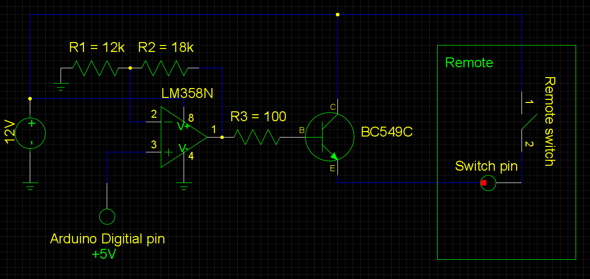
I use power outlets which can be turned on and off by a remote. But instead of pressing the button on the remote, I have attached my Arduino board in order to control the remote from the PC. Replacing the buttons on the remote was a little more complicated than I had thought it would be, because the switches have different voltages on their pins and hence a simple transistor circuit didn’t work for me. In order to get the right base-voltage for the transistors to conduct sufficiently I have put an operation amplifier before the transistor, amplifying the 5V from the Arduino to the 12V used by the remote. In this way the transistor is saturated when the Arduinos pin is set to HIGH, closing the switch on the remote, see schematic below.
The final circuit and the Arduino are shown below. Right now the Arduino runs a simple loop, turning the power outlets on and off and it works like a charm!
The next step is to write an interface which can forward incoming commands to the board. Also my focus will be on security, since this is what is neglected by many “smart home” suppliers.
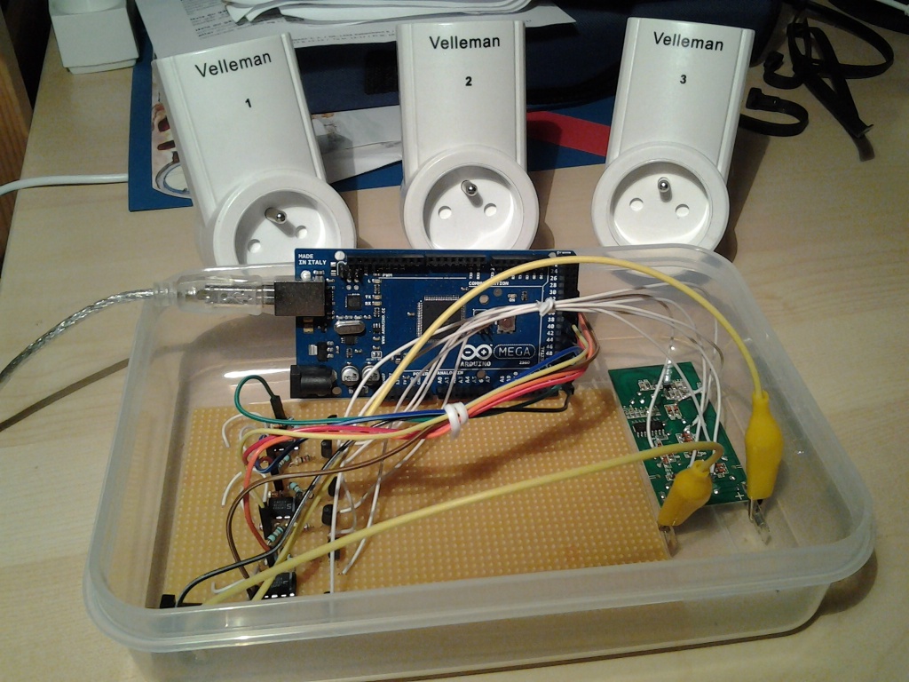 |
| The power outlets in the background, the Arduino Mega board upright, the remote control on the right and the operation amplifier-transistor circuits on the orange board. The board is powered by a 12V-source, drawing 50mA (incl. the remote). |
Comments are closed.